
Build clean. ✅
Segmented Plate Anchor Chair — New "Use WRC 537" Option (v5796)
What changed
For Segmented Plate anchor chair baseplates, MecaStack now offers two methods for checking the local shell (skirt) stress at the bolt locations:
- Legacy method — Brownell & Young, Process Equipment Design, eqn 10.59. This treats the segmented top plate footprint as an effective strip of skirt that resists the bolt load locally.
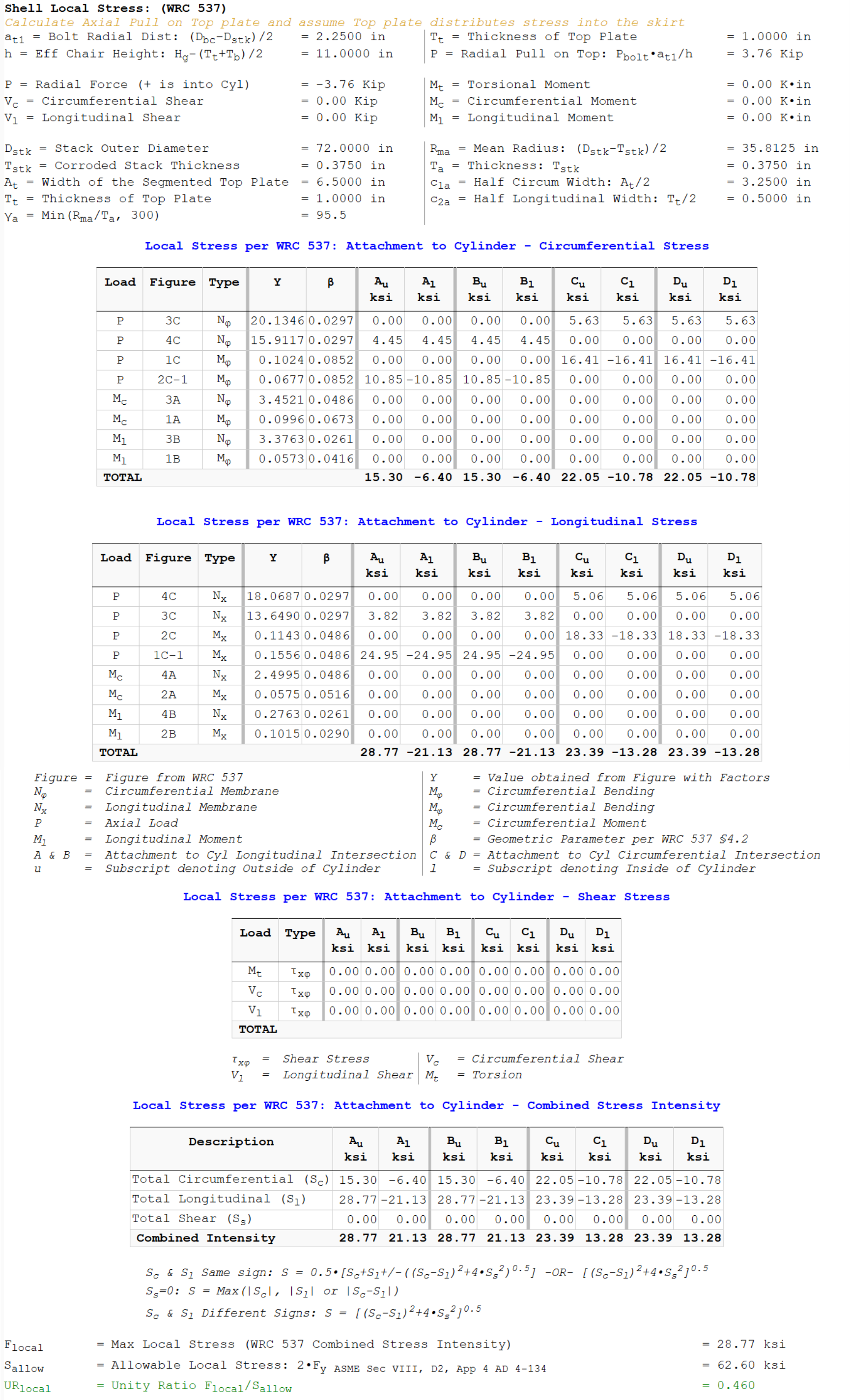
- New method (WRC 537) — The radial pull from each bolt (P = P_bolt · a / h) is applied as a rectangular attachment load on the skirt cylinder, with the segmented top plate's circumferential and longitudinal dimensions defining the attachment footprint. The combined membrane + bending stress intensity is calculated from the WRC 537 curve fits and compared to the ASME Section VIII Division 2, Appendix 4 allowable.
The choice is controlled by a new checkbox in the baseplate input panel labeled "WRC537 — Use WRC 537 for Segmented Chair", located between the Pretension and Number of Bolts inputs (visible only when the baseplate type is set to Segmented Plate).
Why we added it
The Brownell & Young eqn 10.59 strip method was developed for continuous top plates and adapted to segmented chairs by treating each segment's top plate footprint as the effective load-bearing strip. While it captures the right order of magnitude, it does not properly account for:
- The biaxial stress state in the skirt under a localized attachment load (B&Y is essentially uniaxial)
- The interaction between membrane and bending stresses at the attachment footprint
- The shell curvature effect (the skirt's resistance to local bending depends on R/T)
WRC 537 is the industry-standard reference for evaluating local stresses in cylindrical shells caused by external loads applied through rectangular or circular attachments. It is based on extensive shell-theory solutions and parameter studies, and it directly produces the stress intensity at the four critical points around the attachment footprint. The ASME Section VIII Division 2, Appendix 4 framework then categorizes those stresses (primary membrane, primary bending, secondary) and compares to the appropriate allowable.
For a typical segmented chair, switching from B&Y to WRC 537 produces a more accurate (and often less conservative) unity ratio, with a clear traceable reference to a recognized design standard.
How the WRC 537 method works
When the option is enabled, MecaStack:
- Computes the effective lever arm: h = H_g − (T_T + T_b)/2 (mid-top plate to mid-bottom plate).
- Calculates the radial pull at the top plate: P = P_bolt · a / h, where a = (D_bc − D_stk)/2 is the bolt radial offset from the skirt OD.
- Builds a rectangular attachment using the segmented top plate footprint: A_t (circumferential width) × T_T (longitudinal height).
- Runs the full WRC 537 calculation against the skirt cylinder (D_stk, T_stk) for that load and attachment, producing the maximum stress intensity F_local.
- Calculates the ASME Section VIII Div 2 App 4 allowable S_allow from the skirt material's yield (F_y) and ultimate (F_u) strengths at the operating temperature.
- Reports the unity ratio UR = F_local / S_allow.
The full WRC 537 sub-report is included in the calculation output, showing the dimensionless geometry parameters (γ, β1, β2), the curve-fit stress coefficients at each critical point around the attachment, and the membrane-and-bending stress breakdown.
What about my existing models?
Backwards-compatible by design:
- Existing models opened in v5796+ retain the legacy B&Y method. Your saved unity ratios will not change.
- New models created in v5796+ default to the WRC 537 method.
- You can toggle the WRC537 checkbox on any model to switch between methods at any time.
If you want to take advantage of the new method on an existing project, simply check the box and re-run the analysis.
When the WRC 537 method is appropriate
The WRC 537 method is appropriate whenever:
- The baseplate type is Segmented Plate (continuous-plate chairs use a different method — see the Continuous Plate RingCr article).
- The segmented top plate dimensions (A_t and T_T) fall within the parameter ranges of WRC 537 (typical anchor chair geometries are well within these ranges).
- The skirt is welded continuously around the chair attachment.
The WRC 537 method is not intended for segmented plates with unusual geometries (extremely long or narrow top plates) where the parameter range falls outside the WRC 537 curve fits. MecaStack will issue a warning if the geometry parameters are outside the validated range.
Real World Example
Here is an example of a typical stack using the old versus new criteria. This skirt is 0.375 in [9 mm] thick and is producing a unity stress ratio of 1.096, meaning it is at 109.6% of the allowable stress.

The same stack with the new WRC 537 approach, produces a unity ratio of only 0.46 or 46% of the allowable stress.
References
- Welding Research Council Bulletin 537, "Precision Equations and Enhanced Diagrams for Local Stresses in Spherical and Cylindrical Shells Due to External Loadings for Implementation of WRC Bulletin 107," 2010.
- ASME Boiler and Pressure Vessel Code, Section VIII, Division 2, Appendix 4 (Mandatory Design Based on Stress Analysis).
- Brownell, L. E. & Young, E. H., Process Equipment Design, eqn 10.59 (legacy strip method, retained for backward compatibility).
Summary of code changes
| Item | Status |
|---|---|
UseSegmentedWRC537 boolean property declared | ✅ |
Added to UIEntries (between UseContinuousRingCredit and Nbolt) | ✅ |
UI label WRC537, visible only for ChairSeg | ✅ |
Branch in Local(): checked → WRC 537, unchecked → B&Y | ✅ |
New Local_ChairSeg_BY() legacy method added | ✅ |
Constructor default = true (new files) | ✅ |
FileIO LineIO line added | ✅ |
StackFileIO5796 updater extended to also handle UseSegmentedWRC537 (defaults to false for old files) | ✅ |
| VersionHistory entry added | ✅ |
| Build clean (0 errors) | ✅ |
Want me to tweak the article, add specific numbers (typical UR reduction example), or adjust tone?